ISPnub Programming Script Manual
On this page the programming script language for ISPnub, the stand-alone AVR In-System-Programmer module, is described. The steps for programming target controllers are defined within script files. This script files are converted with ISPnubCreator (see ISPnub section "Downloads") into a hex file which is loaded into the flash of ISPnub.Line-based Script File
Script files are line based. Every line contains one command. The following listing shows a example for a ISPnub script file.CONNECT 2000000 ; connect with SCK = 2 MHz SPIVERIFY 0x30, 0x00, 0x00, 0x00, 0x1E ; check signature byte 0x00 (0x1E = manufactured by Atmel) SPIVERIFY 0x30, 0x00, 0x01, 0x00, 0x93 ; check signature byte 0x01 (0x93 = 8KB Flash memory) SPIVERIFY 0x30, 0x00, 0x02, 0x00, 0x07 ; check signature byte 0x02 (0x07 = ATmega8 device) SPIWRITE 0xAC, 0x80, 0x00, 0x00 ; chip erase WAIT 2 ; wait 20 ms FLASH ../test/main.hex, 0, 64 ; flash given hex file starting at flash address 0 with pagesize 64 DISCONNECT ; disconnect SPI DECCOUNTER 10 ; allow 10 programming cycles END
Comments following ";"
Every character in a line after a semicolon (";") is ignored. If a line starts with a semicolon, the whole line is ignored.CONNECT 2000000 ; Comment here! ;this line is ignored DISCONNECT END
Commands
The commands are general ISP functions supported by the Atmel AVR family. This means that ISPnubCreator does not know anything about device specific stuff. It's simple to adopt given example scripts to every AVR controller. Just look into the datasheet of your target controller. The following command descriptions also point to the corresponding section in the datasheet.CONNECT isp_clock_hz
Connect to target device and enable serial programming mode. "isp_clock_khz" defines the SPI clock in Hz used for programming. Internal the nearest possible clock frequency is set. Currently these options are used: 2000000, 500000, 125000, 62500, 4000000, 1000000, 250000.If this command fails, ISPnub stopps further processing and signals the error over LED.
It is possible to use the CONNECT command multiple times in one script file to switch SPI clock while programming, e.g. write fuse bits with low ISP clock and set correct clock option, then DISCONNECT and CONNECT again with higher frequency. Don't forget to close the connection with DISCONNECT before reconnecting again.
Example:
CONNECT 125000                           ; connect with SCK = 125 kHz
DISCONNECT
DECCOUNTER maxcycles
Set decreasing programming counter. With this command you can limit the programming cycles to the given "maxcycles" value. The count of programming cycle is stored within the EEPROM of ISPnub. Every time, ISPnub reaches the DECCOUNTER command, the programming counter is decreased. If the programming counter is zero, no further programming is possible (ISPnub prevents starting script processing) and is signaled over LEDs. The ISPnub must be reprogrammed.DECCOUNTER 150 ; allow 150 programming cycles
DISCONNECT
Disconnect SPI communication to target controller.EEPROM filename, startaddress, pagesize
Program the given hex file to the eeprom of the target device. You have to define the startaddress (eeprom memory address of target) and the page size of the target eeprom memory. The page size is described within the AVR datasheet; search for "Page Size". Example of ATmega644 datasheet: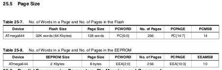
Flash pagesize of ATmega644: 8 bytes
EEPROM main.eep, 0, 8 ; write given hex file to eeprom starting at address 0 with pagesize 8Not all AVRs support page programming for EEPROM! In this case set pagesize to zero. With pagesize set to zero, byte oriented programming is used.
EEPROM main.eep, 0, 0 ; write given hex file to eeprom starting at address 0 with single byte programming
END
Defines the end of the programming script. When this command is reached, the programming process was successful and the programming/error LED is turned off.FLASH filename, startaddress, pagesize
Program the given hex file to the flash of the target device. You have to define the startaddress (flash memory address of target) and the page size of the target flash memory. The page size is described within the AVR datasheet; search for "Page Size". Example of ATmega8 datasheet: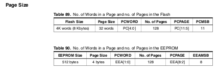
Flash pagesize of ATmega8: 32 words = 64 bytes
FLASH main.hex, 0, 64 ; flash given hex file starting at flash address 0 with pagesize 64
SPIVERIFY b1, b2, b3, b4, v4
Transmit four bytes over SPI to/from target controller and compare the fourth one with given value "v4". If given value is not matching, ISPnub stopps further processing and signals the error over LED.The SPI commands are described in the datasheet for the target controller. Search for a table "Serial Programming Instruction Set" in the datasheet.
Example: Check signature byte of ATmega32A
SPIVERIFY 0x30, 0x00, 0x00, 0x00, 0x1E    ; check signature byte 0x00 (0x1E = manufactured by Atmel)
SPIVERIFY 0x30, 0x00, 0x01, 0x00, 0x95    ; check signature byte 0x01 (0x95 = 32KB Flash memory)
SPIVERIFY 0x30, 0x00, 0x02, 0x00, 0x02    ; check signature byte 0x02 (0x02 = ATmega32A device)
SPIWRITE b1, b2, b3, b4
Write four bytes over SPI to target controller. This command is used to write ISP instructions to the target device.Example: Write a fuse bits to an ATmega8 (value "0x2E"). In the datasheet of the ATmega8 there is a table "Serial Programming Instruction Set" in the section "Memory Programming". We look for the instruction to write fuse bits:
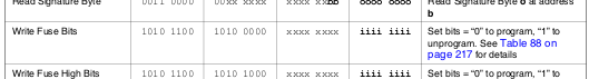
Write fuse bits:
b1 = 0b10101100 = 0xAC, b2 = 0b1010000 = 0xA0, b3 = don't care, b3 = data in
For our example fuse bits "0x2E" we set: b1 = 0xAC, b2 = 0xAC, b3 = 0, b4 = 0x2E
SPIWRITE  0xAC, 0xA0, 0x00, 0x2E          ; write fuse bits
WAIT 1                                    ; wait 10 ms
SPIVERIFY 0x50, 0x00, 0x00, 0x00, 0x2E    ; check fuse bits
The example also shows how to verify the written fuse bits (0x50 is the command for reading fuse bits on ATmega8).
WAIT time_x_10ms
Wait given time before processing the next command. The unit of the given value "time_x_10ms" is 10 milliseconds.Example:
WAIT 3 ; wait 30 ms