Output voltage control of DC/DC converters
Some applications needs to control the output voltage of a dc/dc converter instead using a fixed output voltage. For example battery chargers has to adjust the output voltage to the current battery level. This page shows how to add such a control function to a buck converter circuit.Control output via external voltage source
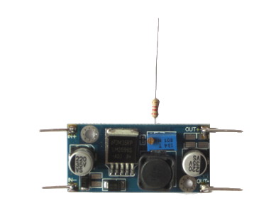
Typically a voltage divider is used in dc converters to adjust the output voltage to the needed feedback voltage. To control the feedback signal by an external voltage source, a third resistor is added to the circuit.A cheap LM2596 converter board is used (pin 4 of LM2596 is the feedback pin):
Calculate resistor network
If there is a fixed resistor to ground and a poti to control the feedback voltage, the additional "control"-resistor can be calculated: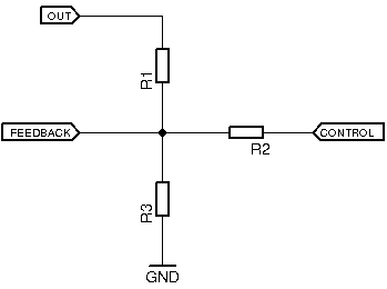
Trim poti for wanted output voltage range
If you use a dc/dc converter board with potentiometer, please note that calibrating the poti with a multimeter is not possible because the resistance cannot be measured in circuit.Steps to set the upper voltage bound:
- Set control voltage to 0V. Note: At 0V I2 is negative.
- Add input voltage to converter board.
- Measure output voltage with multimeter and trim the poti to get the required maximum output voltage.
Use DAC to control output voltage
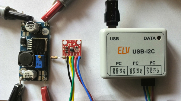
Connect a DAC output via resistor (R2) to the feedback pin of the dc converter chip. Here, a MCP4725 Breakout Board is used which is controlled via an
 ELV USB-I2C-Interface.
The output voltage of the DAC can be set through this interface with serial commands. Example to set 0V DAC voltage (-> maximum output voltage on dc/dc converter):
ELV USB-I2C-Interface.
The output voltage of the DAC can be set through this interface with serial commands. Example to set 0V DAC voltage (-> maximum output voltage on dc/dc converter):
SC0 00 00 PSet maximum DAC voltage (-> minimum output voltage on dc/dc converter):
SC0 0F FF P
Links
Arduino Forum - Control the voltage of a buck converter